I started writing this article while preparing for the pre-2023 OSCP exam, which at the time contained a buffer overflow exploit development. While practicing, I stumbled on a quite curious problem. I went through all the steps to build my exploit, I had the right return address, offsets, bad characters… everything had been done correctly. Yet, my shellcode, encoded with Shikata_ga_nai, was always triggering an access violation. Trying to solve this, I figured out my exploit actually worked perfectly fine when the program was running without the debugger attached, but I was still always getting an access violation within the debugger.
Investigating this issue lead me to dig into Shikata Ga Nai (SGN), together with some googling, in order to understand what was happening. I figured out that…
…it’s not a bug ….. it’s a feature.
The point of this article was originally to address two typical problems OSCP students could run run into when using SGN (at that time, now it may be more for OSED students). The first issue is related to this “feature”, while the second is to understand why we need a NOP sled (and how long should it be).
There are already some very good resources on SGN on the internet. A good review of the state of the art with a list of the most relevant references is provided in Ref. [1], with a presentation of the inner working of SGN. Detailed analyses of the SGN code can also be found in Refs. [2], [3], [4], [5], [6] and [7]. Among these references, the topic of the detection of SGN is discussed in Refs [2], [3], [5] and [6]. Improvements to SGN are proposed in Refs. [1] and [6], and the use of SGN by APT groups is tackled in Ref. [5]. By no means, this small literature review aims at being exhaustive, and there might be other good references available.
But I figured I couldn’t write an article by just providing links to read beforehand and then getting to my point. So I will first present and explain in detail SGN, in a way that I hope is accessible and understandable to beginners (and I will fatally be repeating some of the information from those articles).
Readers will need to have some minimal knowledge of how shellcodes work, of some x86 assembly, and understand why you may need an encoder. Note that I wrote a previous article on how to build a simple XOR encoder/decoder, meant to be an introduction to this one, and which introduces some notions discussed below
Setting up a testing environment
To study SGN, we will need a host program to execute our shellcode. I quickly describe in this section the program I use for that purpose, but this is not the point of this article (and you may safely skip this section if you wish).
I could use the program I wrote in my previous article, but I want here to execute the shellcode on the stack to reproduce the same situation as when working on buffer overflows, and demonstrate the problems mentioned in the introduction (access violations). Those would not occur in my previous program since it cleanly allocated an executable memory buffer for the shellcode.
So I wrote another program: it loads a shellcode from a binary file, and simulates a buffer overflow exploit by copying the shellcode on the stack and overwriting the return address of a function by its address. The full source code of my program can be found on my GitHub. I will only detail here the functions that trigger the shellcode execution in the Listing below.
void * getRetAddr(){
   __asm__(
    "mov (%ebp), %eax\n"  // Stack frame base of caller function
    "add $4, %eax \n"     // Return address of the caller function
    );
}

int smashTheStack(char *shellcode, size_t shellcodeSize){

  //__asm__("int3 \n"); // If you want a breakpoint

  // Get address of return address
  void * retAddr = getRetAddr();

  // Overwrite return address
  *((char **) retAddr) = retAddr + 4;

  // Copy shellcode
  memcpy( retAddr + 4, shellcode, shellcodeSize);

  // Kaboom
  return 0;

}
The first function, getRetAddr() uses some inline ASM code to retrieve the return address in its caller function. I used AT&T syntax here as it seems to be the default for inline ASM in gcc. This code is equivalent to the following code in Intel syntax:
mov eax, [ebp] ; Stack frame base of caller function
add eax, 4     ; Return address of the caller function
Inside this function, the frame pointer EBP points to the top of the stack frame for smashTheStack(), where was pushed the saved value of EBP itself in this function and just above the return address to that same function. Now, [ebp] points to the top of the stack frame for the main() function, caller of smashTheStack(), just above the return address to main()from smashTheStack(). This is precisely what we want to overwrite, and is therefore located at [EBP] + 4.
The small inline ASM code computes precisely this into EAX, which is where the register used to store return values from function calls. So when we call getRetAddr() from smashTheStack(), we then obtain the address of the stored return address. We then overwrite it by the address just after, and place there the shellcode with memcpy(). When the function returns, it jumps to the shellcode.
We then compile this program for Windows with specific parameters to disable protections:
┌──(kali㉿kali)-[~/blog/2-shikata_ga_nai]
└─$ i686-w64-mingw32-gcc -o stack.exe stack-executor.c  -fno-stack-protector -no-pie
Note: You might also have a problem with the DEP (Data Execution Prevention), which prevents code execution on the stack. In that case you can use editbin from Visual Studio to deactivate DEP on the stack.exe by running editbin.exe /NXCOMPAT:NO stack.exe, or by disabling DEP on the whole system in Windows Security>App & Browser Control>Exploit Protection>Exploit protection settings>Data Execution Prevention (DEP). By the way, needless to say you should only be doing any of this in a dedicated VM….. right ?
We can now generate an encoded shellcode with msfvenom, and add a NOP sled (I will explain explain why later) followed by a software breakpoint (opcode 0xCC, see https://en.wikipedia.org/wiki/INT_(x86_instruction)#INT3) at the beginning of the decoder to ease our task.
┌──(kali㉿kali)-[~/blog/2-shikata_ga_nai]
└─$ msfvenom -p windows/exec CMD='cmd /c echo blah' EXITFUNC=process -f raw -e x86/shikata_ga_nai -o shikata-cmd.bin
[-] No platform was selected, choosing Msf::Module::Platform::Windows from the payload
[-] No arch selected, selecting arch: x86 from the payload
Found 1 compatible encoders
Attempting to encode payload with 1 iterations of x86/shikata_ga_nai
x86/shikata_ga_nai succeeded with size 228 (iteration=0)
x86/shikata_ga_nai chosen with final size 228
Payload size: 228 bytes
Saved as: shikata-cmd.bin


┌──(kali㉿kali)-[~/blog/2-shikataganai]
└─$ cat <( python3 -c 'print(23 * "90" + "CC")' |xxd -p -r) shikata-cmd.bin > shikata-cmd-dbg.bin
Meet Shikata Ga Nai
Shikata_ga_nai (SGN) is, from its source, a so called “polymorphic XOR additive feedback encoder”. The SGN module in msfvenom takes a shellcode, encodes it, and generates a new shellcode composed of a decoder stub which will decode the attached encoded payload and then execute it.
I present in this section a general overview of SGN ; we will dive into assembly instructions in the next section.
General structure
There are two parts in the SGN decoder stub: an initialization phase, and a main loop. The initialization phase performs three different tasks in three different blocks of code: retrieving the value of EIP, loading the decryption key in a register, and preparing the counter for the main loop.
Retrieving EIP is critical for a decoder as it needs to know at which memory address the encoded buffer is located. Since the encoded buffer is just attached to the decoder stub, and if the decoder manages to get its own memory address, then it can compute the memory address of the encoded buffer by just adding the right offset. This offset will just be the number of bytes between the beginning of the encoded buffer and the instruction whose memory address was retrieved.
After the initialization phase comes the main loop, where the encoded buffer is decoded in place with a XOR instruction and where the additive feedback is perform.
XOR additive feedback
SGN encodes and decodes its payload with a XOR operation, as in my previous article: the encoded buffer is divided in chunks of 4 bytes (DWORD) and each chunk is encoded (and decoded) by XOR-ing it against a key stored in a register. The difference here is that the key is updated at each iteration of the main loop by adding to it the last decoded DWORD modulo 232 (the additive feedback). As a result, each DWORD of the encoded buffer is effectively encoded with a different key.
Getting EIP through FPU instructions
To retrieve EIP, some decoders and shellcodes use the same CALL-POP trick as I used in my previous article. On the other hand, SGN relies on specific instructions of the Floating Point Unit of the processor (FPU). You could think of the FPU as a secondary processing unit whose role is to perform floating point arithmetic operations. The FPU has its own registers, including one named the FPU Instruction Pointer register (FIP) which keeps a record of the address of the last FPU instruction that was executed. Also, among all available FPU instructions, there are two specific instructions, FSTENV and FNSTENV that dump to a given memory address the “FPU environment”, which contains some of the FPU registers to provide indications on the FPU internal state…. and contains this FIP.
The way SGN retrieves EIP is to first execute an arbitrary FPU instruction, which will store the current value of EIP into FIP, and then execute FNSTENV with a memory location specifically crafted so that FIP will be aligned with ESP (the top of the stack). The address of the first FPU instruction can then be obtained by just popping the value on top of the stack into a register.
This approach kills two birds with one stone by providing on top of this a protection against reverse engineering and analysis, as I will explain at the end of this article (this, by the way, is the “feature” responsible for those access violations).
Polymorphism
Shikata_ga_nai also is “polymorphic”, which, as it name suggests, stands for the fact that every time you will run it, the generated decoder stub will be different. The algorithmic logic will always be the same, but the instructions, the registers and even to some extent the order of the instructions will always be different at each run.
I will discuss more about the implications of the additive feedback and about the polymorphism at the end of this article. Let’s now dissect Shikata_ga_nai.
Dissecting Shikata_ga_nai
Let’s now disassemble our shellcode and focus on the decoder stub.
┌──(kali㉿kali)-[~/blog/2-shikataganai]
└─$ objdump -D -b binary -m i386  -Mintel shikata-cmd-dbg.bin
[...]
00000000 <.data>:
   0:   90                      nop
[...]
  16:   90                      nop
  17:   cc                      int3
  18:   bf c2 78 a2 23          mov    edi,0x23a278c2
  1d:   da ce                   fcmove st,st(6)
  1f:   d9 74 24 f4             fnstenv [esp-0xc]
  23:   5a                      pop    edx
  24:   33 c9                   xor    ecx,ecx
  26:   b1 33                   mov    cl,0x33
  28:   83 ea fc                sub    edx,0xfffffffc
  2b:   31 7a 0f                xor    DWORD PTR [edx+0xf],edi
  2e:   03 7a cd                add    edi,DWORD PTR [edx-0x33]
  31:   9a 57 df 39 d8 98 20    call   0x2098:0xd839df57
  38:   b9 bd 11 c5 88          mov    ecx,0x88c511bd
  3d:   fd                      std
[...]
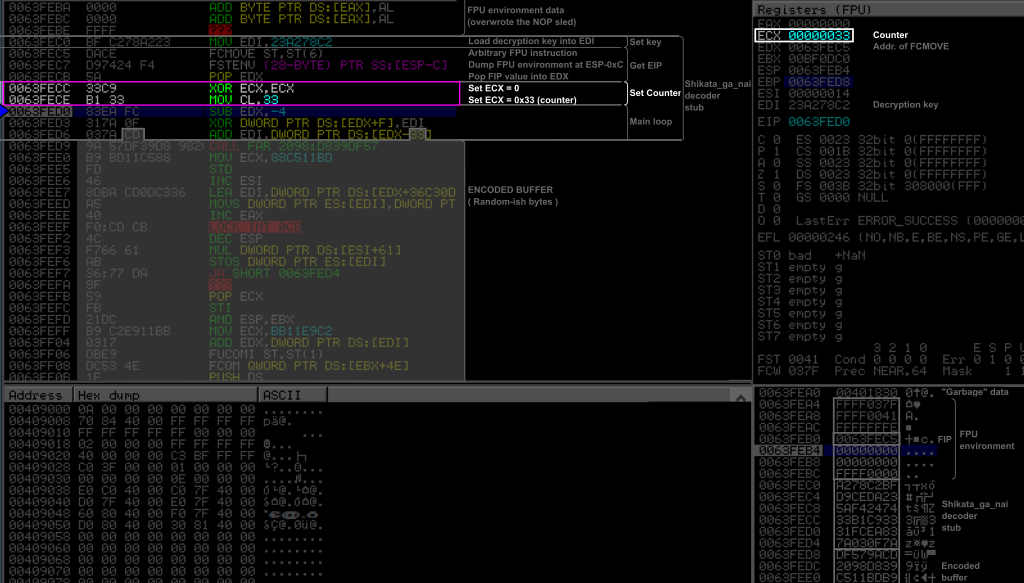
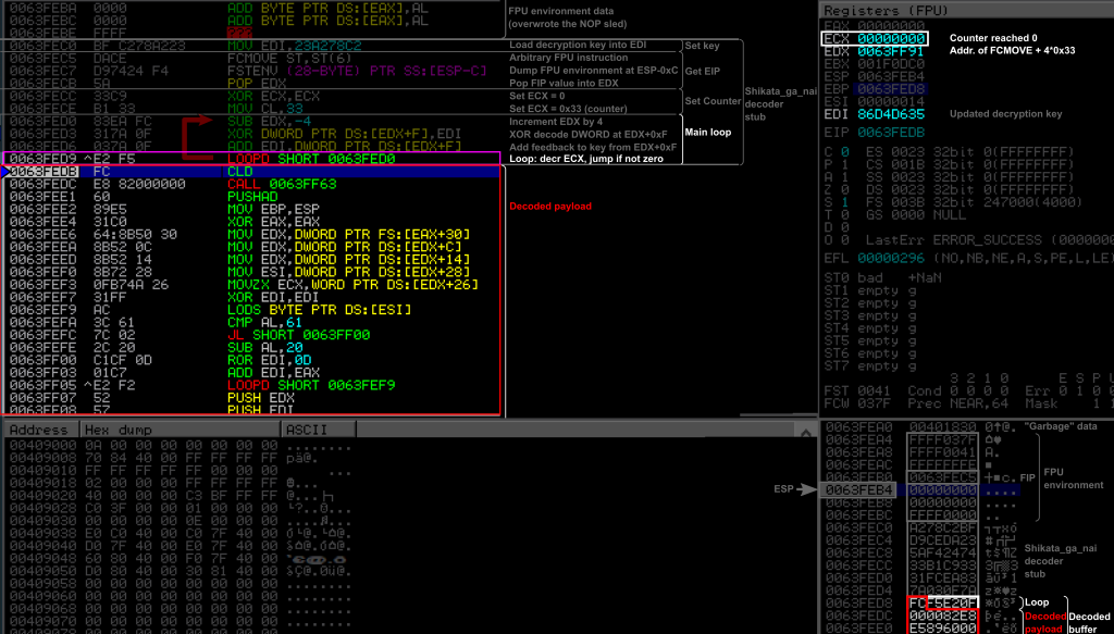
On the Windows VM, we run our shellcode host program stack.exe within Immunity Debugger, and specify our shellcode file shikata-cmd-dbg.bin as argument. We let it run and the debugger automatically pause just after the software breakpoint. The figure below shows a view of the debugger with some annotations I made. I will explain in detail each instruction afterwards, one by one.

On the top left panel, where the assembly instructions are listed, we first see the NOP sled and the breakpoint. Hereafter I will indicate the last executed instruction by a purple rectangle, and the next instruction to be executed by a blue arrow on the left. I will also highlight important elements at each step to try to make the whole picture more readable.
Here, we just “executed” the breakpoint INT3, and are about to execute the first instruction of the decoder at 0x0063FEC0 where starts the SGN decoder stub. This decoder begins with the three initialization blocks (Load encryption key, get EIP, setup counter) followed by the main loop. The encoded buffer is just attached to the end of the decoder stub, and starts at 0x0063FED8. As we will see in detail later, the last bytes of the main loop are themselves encoded: the last operand of the ADD instruction at 0x0063FED6 is actually encoded, as well as the LOOP instruction. We can notice that the encoded buffer contains invalid instructions (in red).
In the bottom right panel, the current state of the stack is represented. The top of the stack is indicated by the ESP arrow, and I am voluntarily showing the stack up to 4 DWORDs above its top, for a reason that will appear later. These bytes are currently filled with residual values (“garbage”). We are right now executing our shellcode similar to a typical buffer overflow situation where the top of the stack points precisely to the beginning of our shellcode (as if we would have returned to a JMP ESP instruction). We can therefore find all our shellcode (NOP sled, breakpoint, decoder, and encoded buffer) in the stack as indicated (keep in mind the little endianness).
Let’s execute and analyze these instructions one by one.
Loading the key
0X0063FEC0: BF C2 78 A2 23 MOV EDI,0X23A278C2
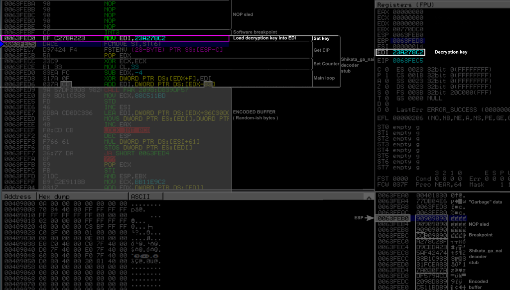
This first instruction simply is the unique instruction of the “Get EIP” block. It simply loaded the value 0x23a278c2 into the EDI register. This is the decryption key, or rather, as we will see later, its initial value.
Getting EIP with FPU instructions
The next three instructions are used to retrieve the value of the EIP register, in order to locate the memory location of the payload to decode.
0X0063FEC5: DA CE FCMOVE ST,ST(6)
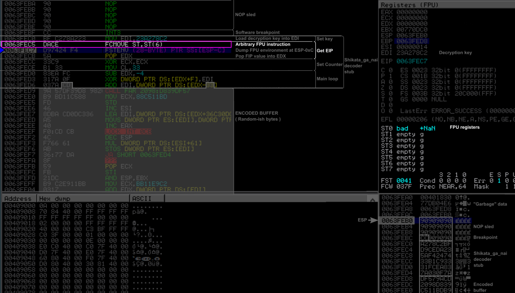
Here, SGN first executed the FCMOVE. It is a conditional move between the FPU internal registers ST and ST6. If we take a look at the registers (top right panel), we can indeed see that this instruction modified the FPU registers (ST0, and FST) in the bottom. But it doesn’t actually matter what this instruction does, the important thing is that the address of this instruction was stored in the FIP register of the FPU (even though FIP is not shown in the debugger).
0X0063FEC7: D9 74 24 F4 FNSTENV [ESP-0XC]
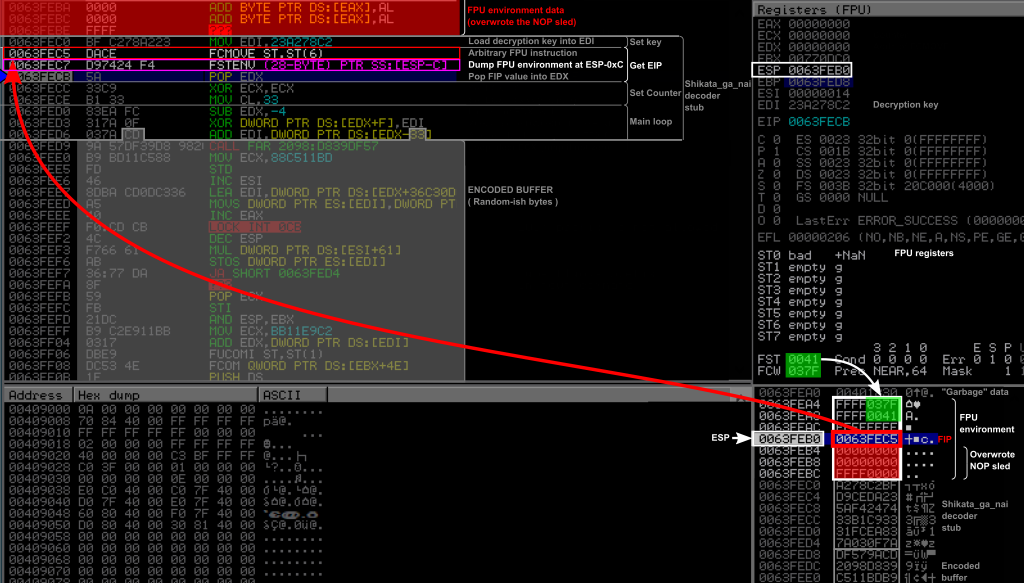
Then comes the FNSTENV instruction. This instruction dumped the “FPU environment” to a specified memory location, here at ESP - 0xC. Since the shellcode has no knowledge of any writable memory page besides the stack, specifying an address on it seems the most practical solution (and we can access these data with POP instructions or by using registers EBP and ESP). Having a look at the data structure of the FPU environment (see this answer, referring to Figure 8-9 on page 8-11 of this manual), we see it is a 28 bytes long structure and that FIP is located at the 13th byte (offset 0x0C = 12).
This first means that it overwrote the stack from 0x0063FEB0 - 0xC = 0x0063FEA4 to 0x0063FEA4 + 27 = 0x0063FEBF (the byte before 0x0063FEC0), as highlighted by a white square on the figure (bottom right panel). We can indeed see that the FPU environment on the stack starts with the values from the FST and FCW registers of the FPU (FPU Status and Control Words respectively), highlighted in green. Note also that this overwrote our NOP sled and our software breakpoint (highlighted in red) as can be seen from the stack (bottom right panel) as well as on the instruction listing (top left panel). This may give you a hint about why you need a NOP sled…
Finally, the FIP value was precisely written at the top of the stack. We can indeed see that the value pointed by ESP on the stack (in a red rectangle) is the address 0x0063FEC5 of the previously executed FVMOVE instruction.
0X0063FECB: 5A POP EDX
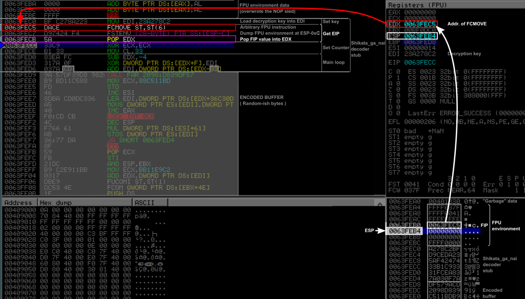
This instruction just popped the FIP value on top of the stack into the EDX register. At this point, the decoder knows the address of its own previous FCMOVE instruction, and can therefore access any byte of itself using the right offset.
Setting a counter for the main loop
0x0063FECC: 33 C9                       XOR    ECX,ECX
0x0063FECE: B1 33                       MOV    CL,0X33
These two instructions just set up a counter in ECX to the size (in DWORDS) of the payload. It just zeroed out ECX with a XOR, and put the initial counter value (here 0x33) in the lower byte of ECX. Proceeding like this is a classical trick to avoid null bytes in shellcodes.
Main loop: advancing the pointer
The next instruction is already part of the main loop, even though it is hard to see it already.
0X0063FED0: 83 EA FC SUB EDX, -4
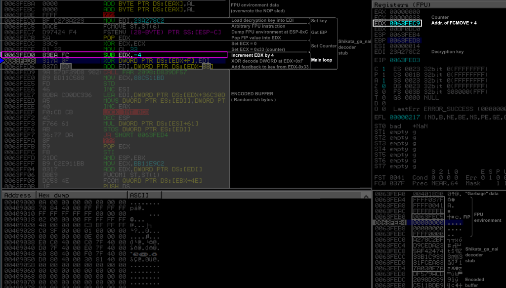
This instruction is an obfuscated way to add 4 to EDX, by subtracting -4. Remember that EDX is the pointer to our shellcode, from which we will access the encoded payload. This instruction actually advanced this pointer to the next DWORD, we will understand later why.
Main loop: XOR decoding
0X0063FED3: 31 7A 0F XOR DWORD PTR [EDX+0XF],EDI
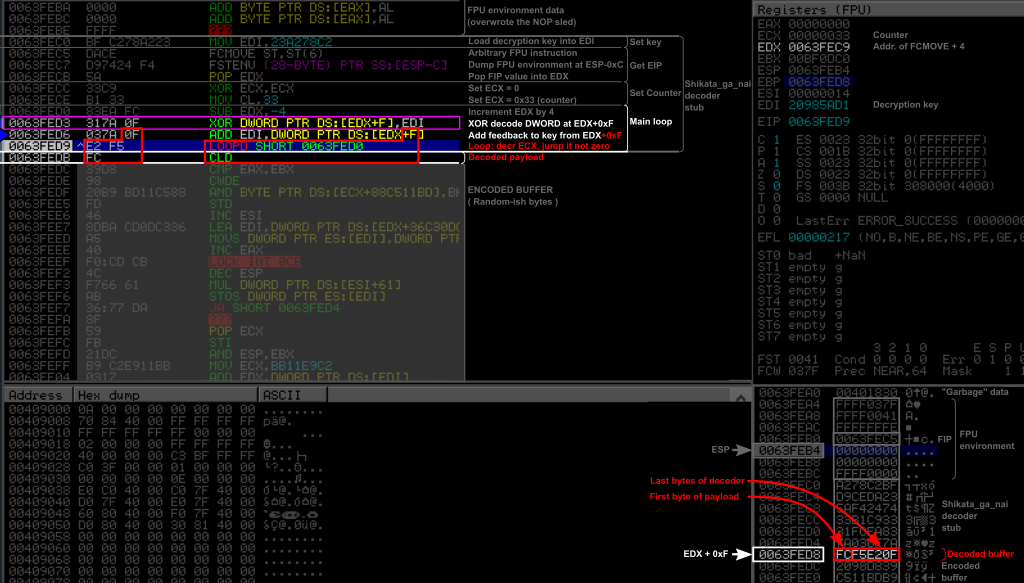
This instruction is the core of the decoder, and is the one that decodes the encoded buffer. Here, it applied an XOR to the DWORD at EDX + 0xF with the value in EDI, which is the (current) key. Since EDX initially pointed to the FCMOVE instruction at 0x0063FEC5, and was then incremented by 4, then the XOR is applied to the DWORD at EDX+0xF = 0x0063FEC5 + 0x4 + 0xF = 0x0063FED8 (or 19 bytes after the FCMOVE instruction), modifying the 4 bytes starting from this address. It means that the last byte of the following ADD instruction is the first byte of the encoded buffer, and was decoded from 0xCD to 0x0F, changing the second operand of this instruction from [EDX-0X33] to [EDX+0xF]. The three following bytes are decoded into two instructions, revealing a LOOPD and a CLD instructions. The LOOPD instruction is the last instruction of the decoder stub, and, as it names suggests, is the looping instruction of the main loop. The CLD instruction is the first decoded instruction of the original payload, as we will see soon.
Main loop: Additive feedback
0X0063FED6: 03 7A CD ADD EDI,DWORD PTR [EDX+0xF]
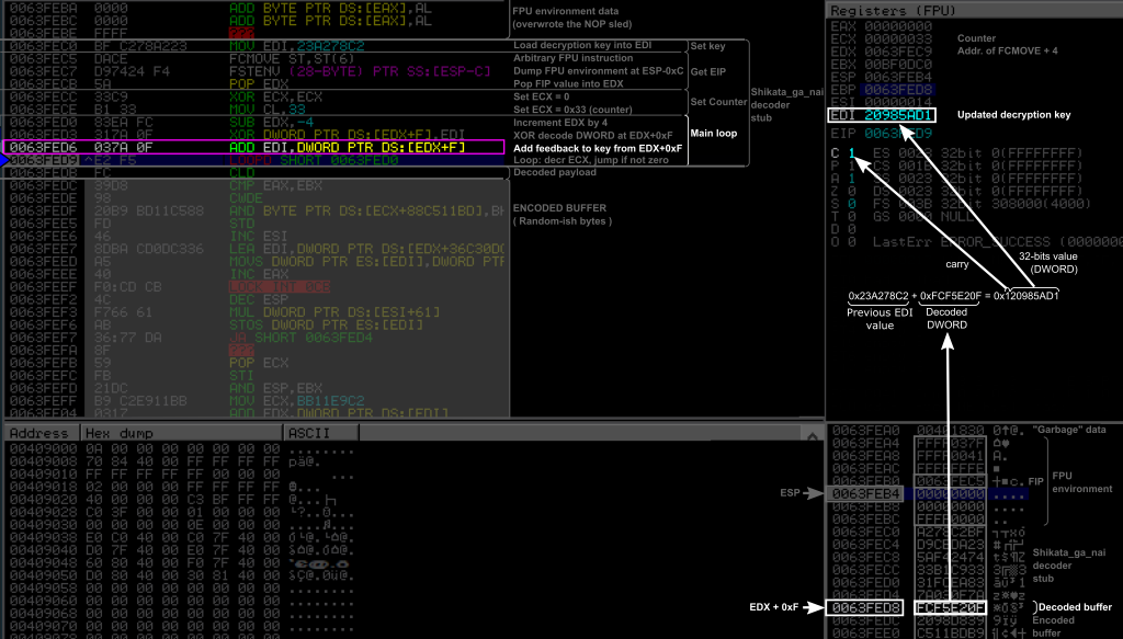
This instruction performed the additive feedback to the key by adding to it the value taken from [EDX + 0xF], which is the DWORD decoded at the previous instruction. So it basically added to the key the clear text that was just decoded. Note that the result of the sum of the original key 0x23A278C2 and of the decoded DWORD 0xFCF5E20F is 0x120985AD1, and requiring 33 bits to be represented. The CPU stores the lower 32 bits into the destination operand (here the EDI register), and turned on the carry flag to indicate a 33rd bit would be necessary to properly represent this result. This carry flag could be used in following arithmetic instructions such as an “add with carry” ADC if big values would have been represented over several DWORDs. In the present case, the carry flag is just ignored, resulting in a simple addition modulo 232.
In the end, we now have a new key in EDI to decode the next DWORD.
Main loop: looping
0X0063FED9: E2 F5 LOOPD SHORT 0x0063FED0

This instruction, which was encoded originally, can be seen as a short hand for DEC ECX and JNZ SHORT 0x0063FED0. It decrements ECX, and jumps to 0x0063FED0 if ECX is not zero. It is basically a for loop counting down to zero based on the value in ECX. When ECX reaches 0, the execution flow just proceeds to the following instruction.
Here it decremented ECX from 0x33 to 0x32, and jumped back to the first instruction of the main loop, the SUB EDX, -0x4. Eventually, what this loop do, is to first advance EDX to the next DWORD with the SUB instruction, decode the DWORD at EDX+0xF by apply the XOR, and update the key by adding to the key the resulting decoded DWORD modulo 232. Since at each iteration of the decoding loop, the key will be updated, it means each DWORD of the encoded buffer is effectively decoded (and thus had been encoded) with a different key.
If we let the decoder go through all the iterations of the loop, here is what we get.
The whole payload has been decoded and the ECX counter has reached 0. The LOOP instruction did not jumped back this time and the execution flow is now entering the original payload. We can notice that the original payload now contains several null bytes, while it didn’t in its encoded form. If we let the execution continue, we indeed see our shellcode being executed and get our “blah” message on the command prompt.
Cool, but why my shellcode doesn’t work ?
Most probably for one of these two reasons.
NOP sleds
The first reason is that you may not have put a NOP sled long enough, or not at all. We saw earlier that the FNSTENV instruction overwrote our NOP sled and the INT3 instruction (breakpoint), which gives us already an idea of the problem. Let’s see what’s happening precisely.
Here, as the shellcode is running on the stack, it uses the same memory space as does the FNSTENV instruction to dump the FPU environment, overwriting 28 bytes of data starting from 12 bytes before ESP (the [ESP-0xC] operand) until 16 bytes after ESP. In this particular execution of SGN, the FNSTENV instruction spans from the 8th to the 11th bytes (included), and thus, in the absence of any NOP sled, would overwrite itself and the three following instructions. We can check it out by executing the same shellcode without NOP sled nor breakpoint, as in the Figure below.
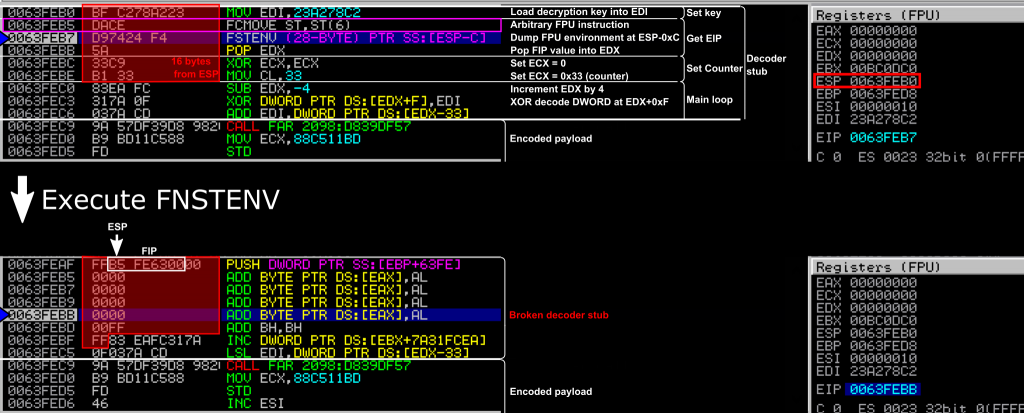
The top of the figure shows the assembly instructions and registers before executing the FNSTENV instruction. ESP points to 0x63FEB0, which is the beginning of the decoder stub. In the red rectangle are the 16 bytes following ESP that should be overwritten. The next instruction to be executed is the FNSTENV at 0x0063FEB7, after which the instruction pointer EIP will be advanced to the next instruction, the POP EDX at 0x0063FEBB.
The bottom part of the figure shows what happens just after executing FNSTENV. At the beginning of the decoder, where ESP points to, we find the FIP value, and the rest of the FPU environment. We see that EIP is now at 0x0063FEBB as expected, but the POP EDX disappeared. It was overwritten by the FPU environment data, which replaced the 0x5A byte of the POP EDX by two null bytes. The CPU will just execute the code located at the address pointed by EIP, and interpret these bytes as code instructions. Here, the null bytes are interpreted as an ADD [EAX], AL which will add the lower 8bits value from EAX into the memory address pointed by EAX. Since the shellcode did not initialize EAX, this will result in something unpredictable, but very likely to cause an access violation sooner or later. For sure, the decoder will not work anymore, and therefore the original payload of the shellcode will never be decoded. Hence, the shellcode will fail.
This happens when the shellcode is close to ESP, especially if you landed there with a JMP ESP instruction. The role of a NOP sled, is to push the shellcode far enough from ESP, and have the NOP sled overwritten by FNSTENV instead of the shellcode.
Remark: Besides the overwritten bytes, the 3 last instructions of the decoder also appear to be completely different, even though the bytes are the same. This is because in x86, instructions don’t have all the same length, so the CPU and the debugger need to decode instructions one by one to know where the next one starts. Here, the single byte 5A that was coding for a POP EDX instruction, was replaced by a null byte that is decoded as an ADD instruction, and is expected to take two bytes. In the end, this all shifted where an instruction starts and where an instruction ends, and the following bytes are interpreted as different instructions.
So how long should the NOP sled be ?
This can easily be computed considering that the instruction following FNSTENV, here POP EDX, must not be overwritten. It is however not a problem if already executed instructions are overwritten… including FNSTENV itself, as it will have already been executed at that time. Since 16 bytes starting from ESP are overwritten, we’ll need a number of NOPs equal to 16 minus the number of bytes between ESP and the beginning of the instruction following FNSTENV. In our case, there are 11 bytes before the POP EDX instruction, so we can just place 5 NOPs before the decoder, as demonstrated in the Figure below.
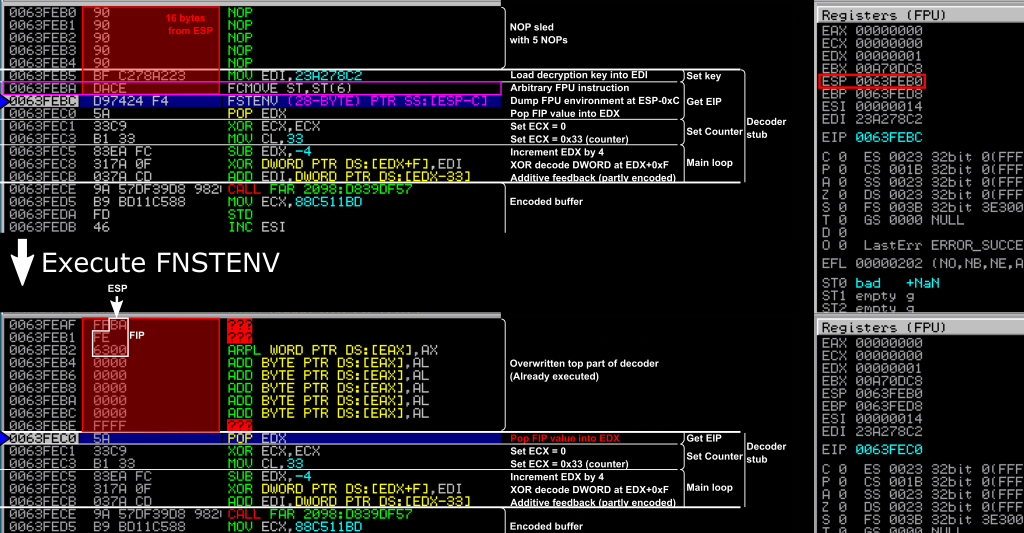
This time, once the FNSTENV instruction is executed, the following POP EDX instruction is not modified, while all instruction before are. The decoder can then proceed and successfully decode the payload.
Protection against reverse engineering with FPU instructions
FPU instructions work well on bare silicon, but they are badly implemented in some emulated environment and debuggers. SGN takes advantage of this to “detect” if it is running in a debugger, and deliberately crash to prevent revealing the encoded payload. Since the payload is encoded and the decoder crashes, it makes hard to analyze the real payload. To quote a conference paper (ISC 2014):
Since most emulators, including S2E/QEMU, do not fully support FPU instructions, they have been used to detect emulated environments.
In practice, what happens is that the FIP value dumped by FSTENV is set to NULL on the stack. When the decoder continues its execution after the FSTENV, it will pop a NULL value into EDX, add 4 to it (setting it to 0x00000004), and then try to XOR the value at that address plus 0xF (so 0x00000013) instead of the address of the encoded payload. This has all the chances to end up in an access violation, especially on modern Windows since the null page cannot be accessed at all in user mode since Windows 8 for security reason. This is shown on the Figure below.
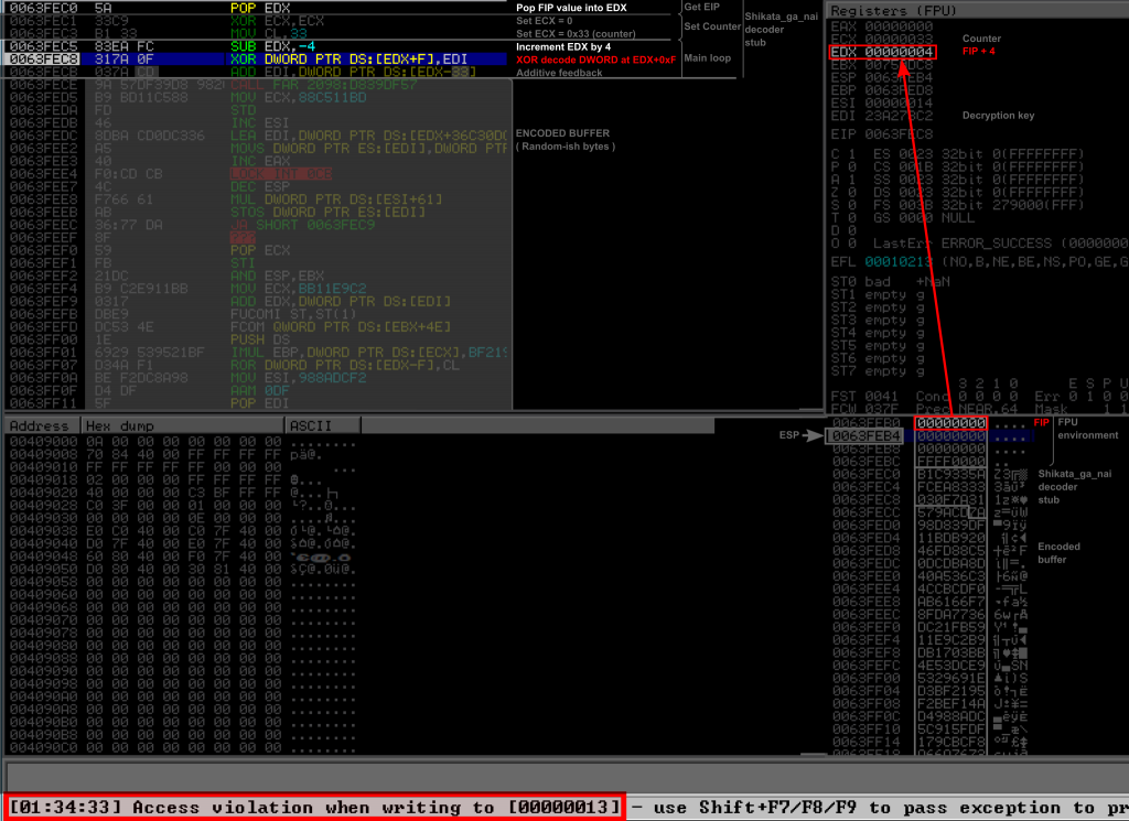
In any way, if the decoder survives this without an access violation, the decoder would only “decode” the buffer at 0x00000004 and not the payload, so when execution would reach the payload, it would sill be encoded.
As said in the introduction, this is not a bug, but a feature. It actually is a protection against reverse engineering, in order to hinder the analysis of the shellcode when it’s run in a debugger.
For some reason, it was the case on the Windows 10 client in the OSCP lab, at least for me. It is not the case on my Windows VM on my laptop, and I have been able to debug SGN without any problem. It seems to depend on the configuration.
To come back to the buffer overflow exploit development, the important point for you is that if you get an access violation at the XOR instruction and involving a very low value address, then you certainly are running into this problem. At this point there is a good chance your exploit is actually working, so just try it without the debugger. If you still want to debug your shellcode or decoder, you can just manually edit the stack after the FSTENV and replace the NULL bytes by the address of the first FPU instruction.
Some more thoughts
Polymorphsim
As I said in the introduction Shikata_ga_nai is “polymorphic” and the decoder stub will be different every time you run SGN. This is made to avoid having a specific pattern signature that could be used by antiviruses to detect it. We can analyze this either by disassembling and analyzing several realizations of SGN, or just by consulting its source code.
The first method is to use different instructions to perform the same thing. As an example a ECX can be cleared either by a XOR ECX, ECX or by a SUB ECX, ECX, and then set to its value by an ADD CL, 0x33 or a SUB CL, -0x33. Same thing to advance the FIP pointer, it can be done either by adding 4 or subtracting -4. Several tricks like this are used to randomly pick instructions that are effectively equivalent. The first FPU instruction, used to initialize FIP, is also picked at random among a list of hard coded instructions, as can be seen from SGN source code:
    0xe8.upto(0xee) { |x| fpus << "\xd9" + x.chr }
    0xc0.upto(0xcf) { |x| fpus << "\xd9" + x.chr }
    0xc0.upto(0xdf) { |x| fpus << "\xda" + x.chr }
    0xc0.upto(0xdf) { |x| fpus << "\xdb" + x.chr }
    0xc0.upto(0xc7) { |x| fpus << "\xdd" + x.chr }

    fpus << "\xd9\xd0"
    fpus << "\xd9\xe1"
    fpus << "\xd9\xf6"
    fpus << "\xd9\xf7"
    fpus << "\xd9\xe5"
With a simple Python script using the Capstone disassembly library, we can obtain the list of corresponding FPU instructions:
fldpi   , fnop    , fldl2t  , fldlg2  , fcmovnu , fcmovnb ,
fld1    , ffree   , fldln2  , fcmove  , fxch    , fcmovne ,
fcmovu  , fld     , fldl2e  , fcmovb  , fcmovbe , fincstp ,
fcmovnbe, fdecstp , fxam    , fabs
The second method is to randomly pick registers to store the key and the FIP pointer. The ECX register is however always used as the counter since the loop relies on the LOOPD instruction.
The third method is to shuffle instructions. I wrote before that there are two parts in SGN: an initialization phase, and a main loop.
In the initialization phase, there are three logical blocks: retrieving EIP, loading the decryption key in a register, and preparing the counter for the main loop. These three blocks are completely independent, and could be executed in any order. The SGN encoder relies on this property to partially shuffle these instructions. From my observations, it seems to always start with the “GetEIP” block, and to insert the instruction “LoadKey” single instruction block a random place before, after, or within the “GetEIP” block. Then comes the “SetCounter” block.
But instructions from different blocks could even be completely mixed and shuffled all together as long as the instructions belonging to the same block are executed in the correct order.
In the main loop, the order of the instructions is also picked at random (to some extent). There are 3 instructions, the XOR that decodes the payload, the ADD that advance FIP, and the ADD that performs the additive feedback. The only restriction is that the additive feedback is performed after the XOR (since the former instruction relies on the result of the latter). Besides this restriction, and provided the offsets of the operands are properly computed, these 3 instructions can be shuffled and executed in any order, which is what SGN does.
To illustrate this, we can have a look at another realization of SGN:
  0: dbdc             fcmovnu st(0), st(4)              ; GetIp Step 1: FPU instr IP: 000
  2: be3a41fa94       mov esi, 0x94fa413a               ; SetKey Step 1: Key stored in ESI, value: 94fa413a
  7: d97424f4         fnstenv [esp - 0xc]               ; GetIp Step 2: Dump FPU env
  b: 5b               pop ebx                           ; GetIp Step 3: FIP register: EBX
  c: 29c9             sub ecx, ecx                      ; SetCounter Step 1: ECX cleared
  e: b133             mov cl, 0x33                      ; SetCounter Step 2: Counter set to 033
 10: 317318           xor dword ptr [ebx + 0x18], esi   ; MainLoop: XOR decode instruction. Encoded bytes start offset: 0x018
 13: 83c304           add ebx, 4                        ; MainLoop: Advance pointer AFTER XOR
 16: 037314           add esi, dword ptr [ebx + 0x14]   ; MainLoop: Key feedback instruction
 19: e2f5             loop 0x10                         ; MainLoop: Loop instruction. Payload start offset: 0x01b
Compared to the decoder we studied in the first part of this article, we can notice that this time the key is loaded into ESI and it is done between the two FPU instructions, the pointer to FIP is stored into EBX. In the main loop, the FIP pointer is incremented after the XOR and before the additive feedback. As a result, the offsets used in the XOR and ADD instructions of the main loop are different, even though they are pointing to the same address (0x18 = 0x14 + 0x4).
As mentioned in Ref. [6], more could be done to render SGN’s code even more unpredictable (for instance not using ECX as a counter).
Multiple iterations
It is possible to use several iteration of SGN while encoding a payload in msfvenom. What happens in practice is that SGN just blindly and independently encodes the previous iteration as if it was a new shellcode. When executed, each decoder decodes its payload and then execute it. For each iteration of SGN, each payload is itself a decoder that does again the same thing. The Listing below shows the code of three iterations of SGN after being decoded:
;------[ Shikata_ga_nai decoder | Iteration 1 ]-----
   0: DAD6             fcmovbe st(0), st(6)             ; GetIp Step 1: FPU instr at offset 000
   2: D97424F4         fnstenv [esp - 0xc]              ; GetIp Step 2: Dump FPU env
   6: 5D               pop ebp                          ; GetIp Step 3: FIP in register EBP
   7: B84A1ACE30       mov eax, 0x30ce1a4a              ; SetKey Step 1: Key stored in EAX, value = 30ce1a4a
   c: 29C9             sub ecx, ecx                     ; SetCounter Step 1: Clear ECX
   e: B140             mov cl, 0x40                     ; SetCounter Step 2: Counter set to 040
  10: 83C504           add ebp, 4                       ; MainLoop: Advance pointer BEFORE XOR
  13: 314516           xor dword ptr [ebp + 0x16], eax  ; MainLoop: XOR decode instruction. Encoded bytes start at offset 0x01a
  16: 034516           add eax, dword ptr [ebp + 0x16]  ; MainLoop: Key feedback instruction
  19: E2F5             loop 0x10                        ; MainLoop: Loop instruction. Payload start at offset 0x01b
;------[ Shikata_ga_nai decoder | Iteration 2 ]-----
  1b: BEB77D7437       mov esi, 0x37747db7              ; SetKey Step 1: Key stored in ESI, value = 37747db7
  20: DADB             fcmovu st(0), st(3)              ; GetIp Step 1: FPU instr at offset 020
  22: D97424F4         fnstenv [esp - 0xc]              ; GetIp Step 2: Dump FPU env
  26: 5A               pop edx                          ; GetIp Step 3: FIP in register EDX
  27: 31C9             xor ecx, ecx                     ; SetCounter Step 1: Clear ECX
  29: B13A             mov cl, 0x3a                     ; SetCounter Step 2: Counter set to 03a
  2b: 83C204           add edx, 4                       ; MainLoop: Advance pointer BEFORE XOR
  2e: 31720E           xor dword ptr [edx + 0xe], esi   ; MainLoop: XOR decode instruction. Encoded bytes start at offset 0x032
  31: 03720E           add esi, dword ptr [edx + 0xe]   ; MainLoop: Key feedback instruction
  34: E2F5             loop 0x2b                        ; MainLoop: Loop instruction. Payload start at offset 0x036
;------[ Shikata_ga_nai decoder | Iteration 3 ]-----
  36: DDC5             ffree st(5)                      ; GetIp Step 1: FPU instr at offset 036
  38: D97424F4         fnstenv [esp - 0xc]              ; GetIp Step 2: Dump FPU env
  3c: BDF4DCD543       mov ebp, 0x43d5dcf4              ; SetKey Step 1: Key stored in EBP, value = 43d5dcf4
  41: 5B               pop ebx                          ; GetIp Step 3: FIP in register EBX
  42: 31C9             xor ecx, ecx                     ; SetCounter Step 1: Clear ECX
  44: B133             mov cl, 0x33                     ; SetCounter Step 2: Counter set to 033
  46: 316B18           xor dword ptr [ebx + 0x18], ebp  ; MainLoop: XOR decode instruction. Encoded bytes start at offset 0x04e
  49: 036B18           add ebp, dword ptr [ebx + 0x18]  ; MainLoop: Key feedback instruction
  4c: 83C304           add ebx, 4                       ; MainLoop: Advance pointer AFTER XOR
  4f: E2F5             loop 0x46                        ; MainLoop: Loop instruction. Payload start at offset 0x051
;----------------[ Decoded payload ]-----------------
  51: FC               cld
  52: E882000000       call 0xd9
  57: 60               pushal

[...]
We can clearly see each decoder, one after the other.
Additive feedback XOR encoding
SGN encodes its payload with a XOR cipher where the key is updated after each iteration.
But why ?
The following is a purely personal speculation from my part, but my guess is that it’s for these two main reasons.
Cryptography
The first reason I could imagine would be for antivirus evasion. The XOR cipher with such a short repeating key is known to be weak (it can be broken with frequency analysis for instance). And even without breaking the key, it could be possible to identify some known payloads thanks to some identifiable artifacts when encoded with a constant key, since all bytes that are 4 bytes apart would be encoded with the same key. If we consider a message (payload) composed of a sequence of DWORDS m[i] and a key k, and the associated cipher DWORDS c[i] = k ^ m[i], then taking advantage of the XOR commutativity and associativity we obtain for any j the following property:
c[j] ^ c[0] = (k ^ m[j]) ^ (k ^ m[0]) = m[j] ^ m[0].
This means that, without even knowing the key, we could identify a known payload. For instance the m[j] ^ m[0] terms could be precomputed for each known payload, and then compared to the c[j] ^ c[0] from a suspicious buffer or file. A known payload could be found, without even having to parse or even identify the decoder.
It seems to me that this sort of approach would however require a significant amount of processing and resources… And I honestly have no real idea of how complex the antiviruses detection processes are today.
The additive feedback might then provide a mean of evasion. Detecting an SGN encoded payload would be near impossible without knowing the initial value of the key, which requires identification and analysis of the decoder.
Practicality
The second reason I can think of, is to lift a limitation on the number of different bytes a payload can contain. I am not talking here about the length of the payload, but about the cardinal of the set of different bytes that can be used within a payload.
To visualize this, let’s take an extreme case. Consider an XOR cipher with a constant one byte long key, and suppose we want to encode a payload that contains all bytes from 0 to 255 (regardless of their position), while we are limited because of one bad characters badChar. For any constant key k that we could chose, it exists one byte b which when encoded would become the bad character, namely b = badChar ^ k. Thus, by keeping a constant key we are sure that certain bytes cannot be encoded.
In reality, most encoders also use a 4 byte key, instead of a single byte, which eventually allows to chose 4 different one byte keys for 4 smaller and independent sets of bytes to encode. But the problem is still the same, just divided into 4 smaller sub problems, and it can be more or less difficult to find a key that works with all bytes of the payload depending on several factors, such as the amount of different bytes in the shellcode or the number of bad characters.
With the additive feedback, we end up with what can be considered a pseudo-random key stream of infinite length. Each byte would then be encoded with a different key. So the amount of different bytes in the payload doesn’t matter anymore.
Bonus: Shikata_Ga_Nai decoder
It is actually quite easy to write a Python script able to decode and disassemble a shellcode encoded with SGN, provided you know it was encoded with SGN. You just need to disassemble and parse the decoder to find the key, the initial counter value and the offset of the payload. Then you can easily decode the payload keeping in mind the additive offset. You can find here a basic script that does that. It worked with the payloads I tried so far and should be able to detect how many iteration of SGN were used. This is the script I used to generate the listing in the section about polymorphism and multiple iterations. You will need to install the Capstone disassembler package for Python.
References
[1] A Bode and J Ermerins. 2020. Modifying Metasploit Shellcode Decoders to Bypass Static Analysis.
https://ermerins.com/docs/shikataganai.pdf.
[2] V Tsyrklevich. 2006. Polymorphic shellcodes at a Glance.
Originally available at https://tsyrklevich.net/research/Polymorphic%20Shellcode%20at%20a%20Glance.pdf.
A presentation of this talk is on Youtube at https://www.youtube.com/watch?v=vcWz47Zfg-c, and the slides can still be found at https://dokumen.tips/documents/polymorphic-shellcode-at-a-glance.html.
[3] D Sauder. 2015. An Analysis of Shikata-Ga-Nai.
https://danielsauder.com/2015/08/26/an-analysis-of-shikata-ga-nai/.
[4] M Valle. 2018. Shikata Ga Nai.
https://marcosvalle.github.io/re/exploit/2018/08/25/shikata-ga-nai.html.
[5] Mandiant. 2019. Shikata Ga Nai Encoder Still Going Strong.
https://www.mandiant.com/resources/shikata-ga-nai-encoder-still-going-strong.
[6] N Hoffman, J Humble, and T Taylor. 2019. The Shikata Ga Nai Encoder.
Originally at https://www.boozallen.com/c/insight/blog/the-shikata-ga-nai-encoder.html, now available at https://archive.ph/xYnwx.
[7] pcsxcetrasupport3. 2020. More adventures with shell code and the Shikata Ga Nai Encoder.
https://pcsxcetrasupport3.wordpress.com/2020/02/25/more-adventures-with-shell-code-and-the-shikata-ga-nai-encoder/.